
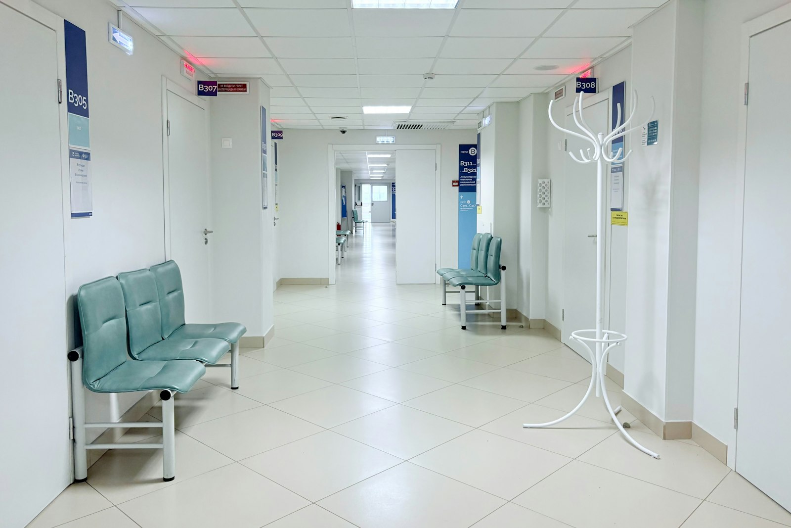
Utility and critical room intelligence for one of India's top hospital chains
This engagement brings one flagship hospital of a leading Indian chain onto Aqueduct. The scope covers 200 measurement points and 1,868 delivered metrics across water, medical gas, electricity, the chilled water plant, the air side and 15 critical rooms. It is designed to hold each utility as a balance, read only, using 134 existing meters and units.
One of India's top hospital chains, with 22 hospitals and 9 clinics, chose one flagship hospital to prove how its utilities and critical rooms can be held on one platform. The hospital occupies ten levels. Water arrives from a municipal connection and two borewells and passes through treatment and two reverse osmosis units, and no existing water meter on that train can be integrated. Oxygen reaches patients from three sources, with no record of what each one contributes.
Electricity and HVAC were the opposite case. Both were metered and controlled through a building management system, yet the 20 floor energy meters sat with their communication ports vacant, and the system displayed the chilled water plant without keeping a record. Fifteen critical rooms, including the operating theatres, the sterile area and the isolation rooms, were certified periodically and unobserved between validation visits.
The scope covers 200 measurement points and 1,868 delivered metrics. Aqueduct instruments only what cannot be read today: water, medical gas, the gas plant panel and the critical rooms. The rest, 134 existing meters, controllers, drives and units across the electrical estate, the chiller plant and the air side, is integrated with no field instrument bought for it. An aQ node reads beside the building management system and writes nothing.
That read only boundary is deliberate. Control is excluded by design and by contract, so the platform can join the utility estate without entering the hospital's clinical risk assessment, and where the building management system raises its own alarm, that alarm stays the operational one. Delivery is planned in six phases, with medical gas work fitted around the clinical calendar.
The design holds each utility as a balance: water from three sources to end use, oxygen supplied against oxygen drawn across three sources and seven floors, floor wise energy on ten levels, chiller plant efficiency as a continuous figure, and 80 air side units and 3 fans on record. A theatre losing positive pressure becomes a timed, recorded event, and aQ Assurance turns room, gas, generator and water quality records into a continuous history for the hospital's own assessments.
No savings figure is stated. The commitment is a measured baseline over the first ninety days, then a joint review against the hospital's own bills, with the template designed to extend across the network.
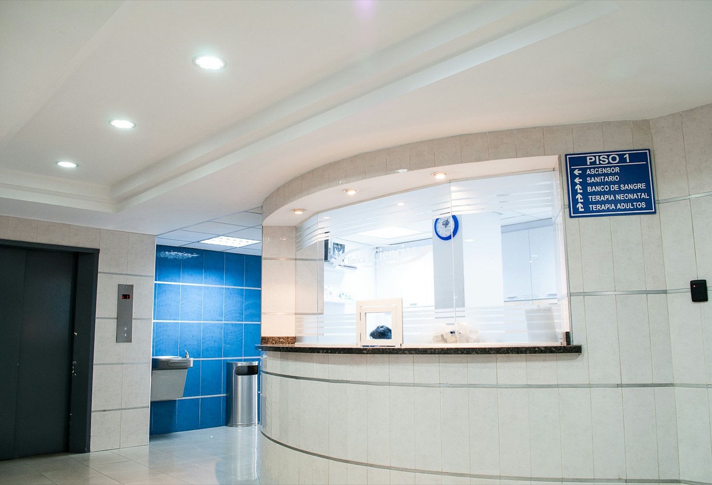
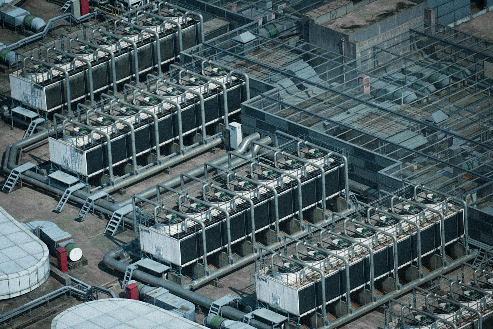
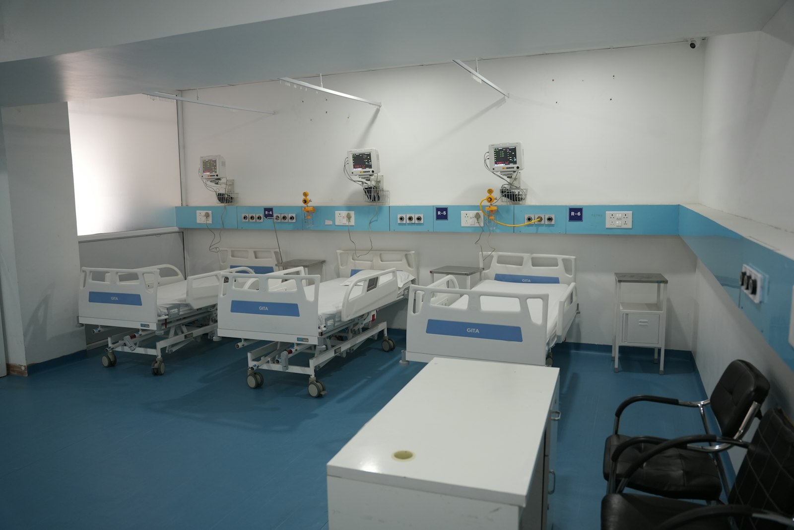

Flagship hospital, ten levels
One hospital in a chain of 22 hospitals and 9 clinics is mapped floor by floor in aQ Core.
Instrument only the blind spots
New devices go only where nothing can be read today. 134 existing meters and units are integrated as they are.
Every utility as a balance
Water, oxygen, electricity and cooling are each held as supply against use, read only.
Pressure excursion recorded
A theatre losing positive pressure becomes a timed, attributable event instead of a gap between certificates.
A standing list, not a discovery
Failed starts, valves not following commands and units left in manual are flagged from the air side record.
Baseline, then the bills
A measured baseline over the first ninety days is followed by a joint review against the hospital's own bills.
How it works at One of India's top hospital chains.
Critical utilities that were metered, but not kept or compared
The hospital spans ten levels. Water comes from a municipal connection and two borewells, passes through treatment and two reverse osmosis units, and none of the existing water meters could be integrated. Oxygen reaches patients from three sources with no record of what each one contributes.
Electricity and HVAC were the opposite case. Both were metered and controlled through a building management system, but the floor energy meters had vacant communication ports and the system displayed the plant without keeping a record. Fifteen critical rooms were certified periodically and unobserved between visits.
- No water balance from source to end use
- Oxygen from three sources with no record of each one's share
- Floor energy meters installed but never read
- Chiller plant shown on screen but not recorded
- Critical rooms seen only at validation visits
Every utility held as a balance, on one platform, read only
Aqueduct instruments only what cannot be read today: water, medical gas, the gas plant panel and the critical rooms. Everything else is integrated from what already exists, including 20 floor energy meters, the chilled water plant and 83 air side units and fans, with no field instrument bought for them.
An aQ node reads beside the building management system without writing to it. The platform reads, records and alerts, and control is excluded from this scope. aQ Assurance organizes room, gas, generator and water quality records into a continuous history for the hospital's own assessments.
- 01
Water balance and gas plant baseline
New flow, pressure and quality instruments close the water balance from three sources to end use, and the gas plant panel is metered.
- 02
Floor energy meters
The 20 existing floor meters are read through their vacant ports, giving floor wise energy on ten levels from meters the hospital already owns.
- 03
Plant and air side beside the BMS
An aQ node reads the chillers, pumps, BTU meters and air side units beside the building management system, read only.
- 04
Critical rooms
15 air quality monitors and 11 differential pressure sensors watch the theatres, sterile area and isolation rooms between validation visits.
- 05
Medical gas
Source and floor gas meters are fitted around the clinical calendar, with permits and re-certification for each intervention.
| Layer | What the scope delivers |
|---|---|
| Water | Source, treatment and reverse osmosis metering for a balance from source to end use |
| Medical gas | Oxygen supplied against oxygen drawn, across three sources and seven floors |
| Electricity | Source wise and floor wise energy on ten levels, with generation kept apart from consumption |
| Chilled water plant | Cooling produced against electricity used, as a continuous efficiency figure |
| Air side | 80 air side units and 3 fans on record with state, conditions, commands and setpoints |
| Critical rooms | Air quality and pressure differentials in 15 critical rooms |
| Boundary | Read only by design and by contract. Nothing is written to any system |
Expected outcomes
The engagement is designed to give the hospital a measured baseline over the first ninety days, followed by a joint review against its own bills. No savings figure is stated before that baseline exists.
The soft value does not wait for a baseline. Pressure excursions become timed, attributable events, plant left in manual becomes a standing list, and environment of care evidence becomes continuous instead of point in time.
- A water balance from three sources to end use
- Oxygen supplied against oxygen drawn, by source and floor
- Chiller plant efficiency as a continuous measured figure
- Failed starts, valves not following commands and units left in manual flagged
- Continuous conditions in 15 critical rooms
Once the flagship hospital is live, the same template is designed to extend across the network, including acquired hospitals. A controls workstream for chiller staging, air handling schedules and critical room pressurization is defined as a future phase, where control is enabled, with owner approval.
From the field to a verified result.
What changed on site.
- No water balance from source to end use
- Oxygen from three sources with no record of each share
- Floor energy meters installed but never read
- Critical rooms seen only at validation visits
- Water held as a balance from three sources to end use
- Oxygen supplied against oxygen drawn, by source and floor
- Floor wise energy on ten levels from meters already owned
- Continuous conditions in 15 critical rooms
- A read only boundary, by design and by contract, lets a hospital add utility intelligence without changing how its clinical systems are controlled.
- Continuous room, gas and water records replace point in time evidence with a history the hospital can show at any assessment.
- Reusing 134 existing meters and units keeps new hardware to the places the hospital is truly blind.
 Logistics and corporate real estate
Water stewardship across Amazon's sites, measured in real time
 Aviation
A top 25 US airport live on Aqueduct in two weeks, with a major leak found at once
 Commercial real estate
Recharge, chiller plant and water intelligence for a 20M+ sq ft developer
Common questions
Aqueduct holds a hospital's utilities as balances on one platform: water from source to end use, medical gas supplied against drawn, floor wise energy and chiller plant efficiency. In this engagement it reads beside the building management system and writes to nothing.
Yes. This scope places air quality monitors and differential pressure sensors in 15 critical rooms, so a theatre losing positive pressure or an isolation room losing negative pressure becomes a recorded event. It is monitoring, not a life safety system.
Not in this engagement. Control is excluded by design and by contract, so the platform reads, records and alerts. A controls workstream is defined as a future phase, where control is enabled, with owner approval.
Only where the site is blind. Here, 134 existing meters, controllers and units are integrated with no new hardware, and new instruments go only on water, medical gas, the gas plant panel and the critical rooms.
Aqueduct supplies continuous measured evidence and exports for an assessment period through aQ Assurance. The hospital's quality team and the accreditor remain the authority.
See Aqueduct on your own facility.
Bring a site, a utility bill or a question. We will show you where the loss is.